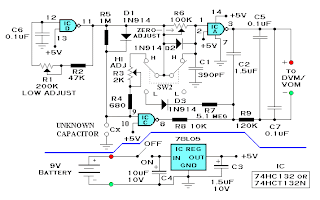
 The schematic shown below measures capacitance from 2.2pF to 1000pF in the L (low) range, and from 1000pF to 2.2uF in the H (high) range. ICD of the 74HC132 (pin 11) produces a 300 Hz square-wave clock. On the rising edge CX rapidly charges through D1. On the falling edge CX slowly discharges through R5 on the L (low) range and through R3-R4 on the H (high) range. This produces an asymmetrical waveform at pin 8 of ICC with a duty cycle proportional to the unknown capacitance; CX. This signal is integrated by R8-R9-C2 producing a dc voltage at the negative meter terminal proportional to the unknown capacitance. A constant reference voltage is produced at the positive meter terminal by integrating the square-wave at ICA, pin 3. R6 alters the symmetry of this square-wave producing a small change in the reference voltage at the positive meter terminal. This feature provides a zero adjustment on the L (low) range. The DVM measures the difference between the positive and negative meter terminals. This difference is proportional to the unknown capacitance.
 Test and Calibration…
Without a capacitor connected to the input terminals, set SW2 to the L (low range) and attach a DVM to the output terminals. Set the DVM to the 2-volt range and adjust R6 for a zero meter reading. Now connect a 1000pF ‘calibration’ capacitor to the input and adjust R1 for a reading of 1.00 volt. Next, switch SW2 to the H (high) range and connect a 1.00uF ‘calibration’ capacitor to the input. Adjust R3 for a meter reading of 1.00 volt. The ‘calibration’ capacitors do not have to be exactly 1000pF or 1.00uF, as long as you know their exact value. Fro instance, if the ‘calibration’ capacitor is known to be .940uF, adjust the output for a reading of 940mV.
All components are 10% tolerance. An LM7805 may be substituted for the 78L05. All fixed resistors are 1/4 watt carbon composition. Capacitors are in uF unless otherwise indicated.